


URDF Design
Differential Drive Robots
- ROS REP conventions
- The root link (main coordinate frmae) must be called
base_link(Coordinate Frames for Mobile Platforms) - The orientation of this link must be:
- x- forward
- y- left
- z- up
- The root link (main coordinate frmae) must be called
Creating the URDF
- Use ROS Snippets to insert Robot element with URDF
<?xml version="1.0"?>
<robot name="robot_name">

</robot>- Specify colors
    <material name="white">
        <color rgba="1 1 1 1" />
    </material>
    <material name="orange">
        <color rgba="1 0.3 0.1 1"/>
    </material>

    <material name="blue">
        <color rgba="0.2 0.2 1 1"/>
    </material>
Base link
The base_link refers to the coordinate frame that represents the main reference point of a robot. It is a standard name used in robot descriptions to define the robot’s body frame in the TF (Transform) tree, which is used to track the spatial relationships between various components of a robot.
Key Characteristics of base_link:
-
Reference Frame of the Robot:
- It serves as the root or origin of the robot’s physical body in the coordinate frame hierarchy.
- Other frames, such as sensor frames (
camera_link,lidar_link) or actuator frames (wheel_link), are typically defined relative to thebase_link.
-
Placement:
- The exact position of the
base_linkis often defined at the robot’s center, such as:- The geometric center of the robot.
- The point of contact with the ground (e.g., the bottom of the chassis).
- A convenient reference point, like the robot’s centroid or center of rotation.
- The exact position of the
<link name="base_link">
</link>
-
Role in Navigation and Localization:
- It is commonly used as the robot’s frame in navigation and localization tasks, making it the frame in which transformations to and from world coordinates (
map,odom) are calculated.
- It is commonly used as the robot’s frame in navigation and localization tasks, making it the frame in which transformations to and from world coordinates (
-
Hierarchy in the TF Tree:
base_linkis often connected to higher-level frames likeodomormap, representing the robot’s position and orientation in the world.
Example TF Tree with base_link:
map
 └── odom
      └── base_link
           ├── camera_link
           ├── lidar_link
           └── wheel_link
 For a differential drive robot it is simplest to treat the center of the two drive wheels as the origin, since the rotation will be centred around this point.
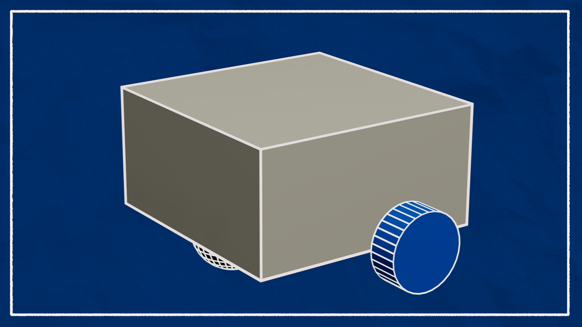
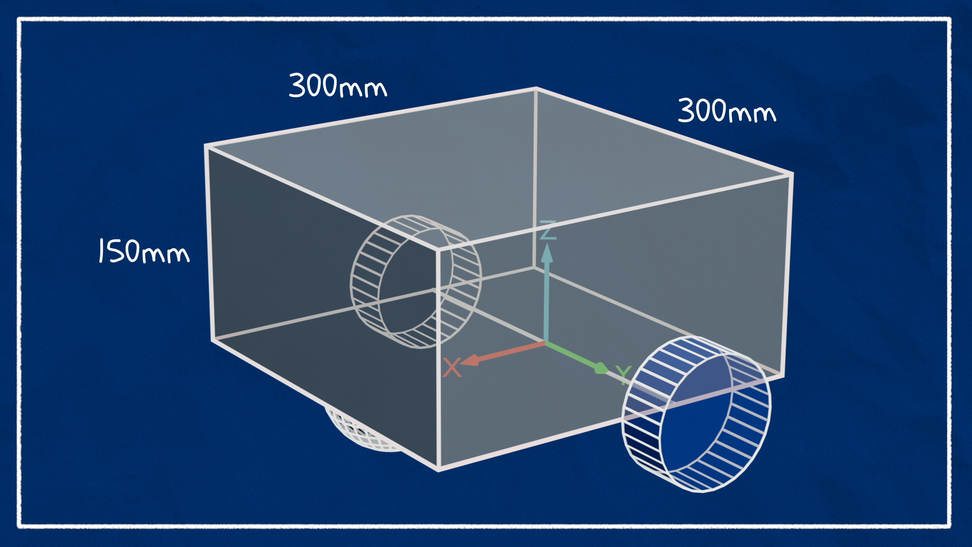
Chassis
We can design the chassis as a box as follows:
- dimensions: 300 x 300 x 150 mm (0.3 x 0.3 x 0.3 m)
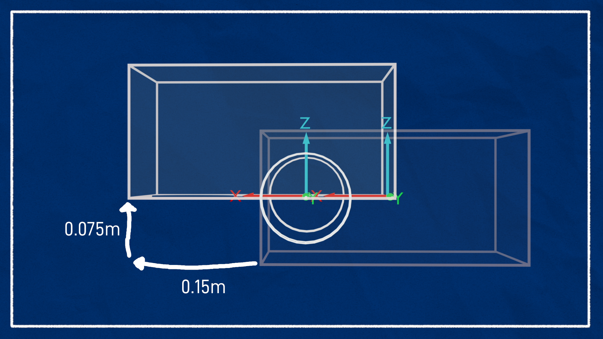
- We want the origin of the chassis to be just behind the center of the 2 drive wheels, so we can set the
chassis_joint-0.1m in x behind thebase_link- But the box geometry will be centered around the chassis origin by default, so we can shift the box forward (in X) by half its length (0.15m), and up (in Z) by half its height (0.075m)

<joint name="chassis_joint" type="fixed">
    <parent link="base_link"/>
    <child link="chassis"/>
    <origin xyz="-0.1 0 0"/>
</joint>

<link name="chassis">
    <visual>
        <origin xyz="0.15 0 0.075" rpy="0 0 0"/>
        <geometry>
            <box size="0.3 0.3 0.15"/>
        </geometry>
        <material name="white"/>
    </visual>
</link>- Current
robot.urdf.xacro
<?xml version="1.0"?>
<robot xmlns:xacro="http://www.ros.org/wiki/xacro" name="robot">

    <material name="white">
        <color rgba="1 1 1 1" />
    </material>
    <material name="black">
        <color rgba="0 0 0 1" />
    </material>
    <material name="orange">
        <color rgba="1 0.3 0.1 1" />
    </material>
    <material name="blue">
        <color rgba="0.2 0.2 1 1" />
    </material>

    <!-- Example link -->
    <link name="base_link"></link>

    <joint name="chassis_joint" type="fixed">
        <parent link="base_link" />
        <child link="chassis" />
        <origin xyz="-0.1 0 0" />
    </joint>

    <link name="chassis">
        <visual>
            <origin xyz="0.15 0 0.075" />
            <geometry>
                <box size="0.3 0.3 0.15" />
            </geometry>
            <material name="black" />
        </visual>
    </link>

</robot>- Create
training_wsif needed
mkdir -p training_ws/src
cd training_ws/src/- clone the repo
git clone git@github.com:Training-Dummy/differential_drive_robot.git
# git clone https://github.com/Training-Dummy/differential_drive_robot.git- Build the package from the root of the workspace (
training_ws)
cd ../..
colcon build --symlink-install --packages-select differential_drive_robot- Source the setup file
source install/setup.bash- Launch the
robot_state_publishernode
ros2 launch differential_drive_robot rsp.launch.py -
Configure RViz settings
- Set fixed frame to
world - Select “Add”, then click
RobotModeldisplay- Set the topic to
/robot_description - Set alpha to 0.8
- Set the topic to
- Select “Add”, then click
TFdisplay- Enable names
- Set fixed frame to
-
Save RViz configuration
- File → save as → navigate to config folder and save the file (e.g.
config/diff-drive.rviz)
- File → save as → navigate to config folder and save the file (e.g.
# cd into training_ws
rviz2 -d src/differential_drive_robot/config/diff-drive.rviz
Drive wheels
The wheels will be connected directly to the base_link (via continuous joints) since it is the center of rotation.
- The wheel origin will be offset from the center by 175mm in y
- The wheel links and have cylinders of 50mm radius and 40mm length
- Since cylinders point upward by default, they need to be rotated 90 degrees about the x axis (roll)
- For the axis of rotation, we want the wheel to spin positive around z axis (which is pointing outwards) when we have a positive motion on the wheels.

    <link name="left_wheel">
        <visual>
            <geometry>
                <cylinder radius="0.04" length="0.05" />
            </geometry>
            <material name="green" />
        </visual>
    </link>


    <joint name="right_wheel_joint" type="continuous">
        <parent link="base_link" />
        <child link="right_wheel" />
        <origin xyz="0.0 -0.175 0.0" rpy="${pi/2} 0.0 0.0" />
        <axis xyz="0.0 0.0 -1.0" />

    </joint>

    <link name="right_wheel">
        <visual>
            <geometry>
                <cylinder radius="0.04" length="0.05" />
            </geometry>
            <material name="green" />
        </visual>
</link>- Note: For RViz to correctly display non-fixed joints (like the wheels), we need joint state publishers to update their positions dynamically
- We can use the
joint_state_publisher_guito publish fake joint states to the/joint_statestopic
- We can use the
ros2 run joint_state_publisher_gui joint_state_publisher_gui
Castor Wheel
The caster wheel will be a frictionless sphere that is connected to the chassis with lowest point matching the base of the wheels
    <joint name="caster_wheel_joint" type="fixed">
        <origin xyz="0.24 0.0 0.0" rpy="0.0 0.0 0.0" />
        <parent link="chassis" />
        <child link="caster_wheel" />
    </joint>

    <link name="castor_wheel">
        <visual>
            <geometry>
                <sphere radius="0.05" />
            </geometry>
            <material name="white" />
        </visual>
    </link>
Collision
- Add collision by copying and pasting geometry and origin from visual tags into collision tags
- Untick “Visual Enabled” and tick “Collision Enabled” to see the collision geometry in RViz
<link name="chassis">
    <visual>
        <origin xyz="0.15 0 0.075" rpy="0 0 0"/>
        <geometry>
            <box size="0.3 0.3 0.15"/>
        </geometry>
        <material name="white"/>
    </visual>
    <collision>
        <origin xyz="0.15 0 0.075" rpy="0 0 0"/>
        <geometry>
            <box size="0.3 0.3 0.15"/>
        </geometry>
    </collision>
</link>
Inertia
- Create a
intertial_macros.xacrofile
<?xml version="1.0"?>
<robot xmlns:xacro="http://www.ros.org/wiki/xacro" >

    <!-- Specify some standard inertial calculations https://en.wikipedia.org/wiki/List_of_moments_of_inertia -->
    <!-- These make use of xacro's mathematical functionality -->

    <xacro:macro name="inertial_sphere" params="mass radius *origin">
        <inertial>
            <xacro:insert_block name="origin"/>
            <mass value="${mass}" />
            <inertia ixx="${(2/5) * mass * (radius*radius)}" ixy="0.0" ixz="0.0"
                    iyy="${(2/5) * mass * (radius*radius)}" iyz="0.0"
                    izz="${(2/5) * mass * (radius*radius)}" />
        </inertial>
    </xacro:macro>


    <xacro:macro name="inertial_box" params="mass x y z *origin">
        <inertial>
            <xacro:insert_block name="origin"/>
            <mass value="${mass}" />
            <inertia ixx="${(1/12) * mass * (y*y+z*z)}" ixy="0.0" ixz="0.0"
                    iyy="${(1/12) * mass * (x*x+z*z)}" iyz="0.0"
                    izz="${(1/12) * mass * (x*x+y*y)}" />
        </inertial>
    </xacro:macro>


    <xacro:macro name="inertial_cylinder" params="mass length radius *origin">
        <inertial>
            <xacro:insert_block name="origin"/>
            <mass value="${mass}" />
            <inertia ixx="${(1/12) * mass * (3*radius*radius + length*length)}" ixy="0.0" ixz="0.0"
                    iyy="${(1/12) * mass * (3*radius*radius + length*length)}" iyz="0.0"
                    izz="${(1/2) * mass * (radius*radius)}" />
        </inertial>
    </xacro:macro>


</robot>- Add the following line near the top of
robot.urdf.xacro
<xacro:include filename="inertial_macros.xacro" />- Add the inertial macros for each link
- You need to specify an
tag (default 0’s) to match the link visual origin. - example:
- You need to specify an
    <link name="chassis">
        <visual>
            <origin xyz="0.15 0 0.075" />
            <geometry>
                <box size="0.3 0.3 0.15" />
            </geometry>
            <material name="black" />
        </visual>
        <collision>
            <origin xyz="0.15 0 0.075" />
            <geometry>
                <box size="0.3 0.3 0.15" />
            </geometry>
        </collision>
        <xacro:inertial_box mass="0.5" x="0.3" y="0.3" z="0.15">
            <origin xyz="0.15 0 0.075" rpy="0 0 0" />
        </xacro:inertial_box>
    </link>
Final robot.urdf.xacro
<?xml version="1.0"?>
<robot xmlns:xacro="http://www.ros.org/wiki/xacro" name="robot">
    <xacro:include filename="inertial_macros.xacro" />

    <material name="white">
        <color rgba="1 1 1 1" />
    </material>
    <material name="black">
        <color rgba="0 0 0 1" />
    </material>
    <material name="orange">
        <color rgba="1 0.3 0.1 1" />
    </material>
    <material name="blue">
        <color rgba="0.2 0.2 1 1" />
    </material>
    <material name="green">
        <color rgba="0 0.3 0 1" />
    </material>


    <!-- Example link -->
    <link name="base_link"></link>

    <joint name="chassis_joint" type="fixed">
        <parent link="base_link" />
        <child link="chassis" />
        <origin xyz="-0.1 0 0" />
    </joint>

    <link name="chassis">
        <visual>
            <origin xyz="0.15 0 0.075" />
            <geometry>
                <box size="0.3 0.3 0.15" />
            </geometry>
            <material name="black" />
        </visual>
        <collision>
            <origin xyz="0.15 0 0.075" />
            <geometry>
                <box size="0.3 0.3 0.15" />
            </geometry>
        </collision>
        <xacro:inertial_box mass="0.5" x="0.3" y="0.3" z="0.15">
            <origin xyz="0.15 0 0.075" rpy="0 0 0" />
        </xacro:inertial_box>
    </link>

    <joint name="left_wheel_joint" type="continuous">
        <parent link="base_link" />
        <child link="left_wheel" />
        <origin xyz="0.0 0.175 0.0" rpy="-${pi/2} 0.0 0.0" />
        <axis xyz="0.0 0.0 1.0" />
    </joint>

    <link name="left_wheel">
        <visual>
            <geometry>
                <cylinder radius="0.04" length="0.05" />
            </geometry>
            <material name="green" />
        </visual>
        <collision>
            <geometry>
                <cylinder radius="0.04" length="0.05" />
            </geometry>
        </collision>
        <xacro:inertial_cylinder mass="0.1" radius="0.04" length="0.05">
            <origin xyz="0.0 0.0 0.0" rpy="0.0 0.0 0.0" />
        </xacro:inertial_cylinder>
    </link>


    <joint name="right_wheel_joint" type="continuous">
        <parent link="base_link" />
        <child link="right_wheel" />
        <origin xyz="0.0 -0.175 0.0" rpy="${pi/2} 0.0 0.0" />
        <axis xyz="0.0 0.0 -1.0" />

    </joint>

    <link name="right_wheel">
        <visual>
            <geometry>
                <cylinder radius="0.04" length="0.05" />
            </geometry>
            <material name="green" />
        </visual>
        <collision>
            <geometry>
                <cylinder radius="0.04" length="0.05" />
            </geometry>
        </collision>
        <xacro:inertial_cylinder mass="0.1" radius="0.04" length="0.05">
            <origin xyz="0.0 0.0 0.0" rpy="0.0 0.0 0.0" />
        </xacro:inertial_cylinder>
    </link>

    <joint name="caster_wheel_joint" type="fixed">
        <origin xyz="0.24 0.0 0.0" rpy="0.0 0.0 0.0" />
        <parent link="chassis" />
        <child link="caster_wheel" />
    </joint>

    <link name="caster_wheel">
        <visual>
            <geometry>
                <sphere radius="0.05" />
            </geometry>
            <material name="white" />
        </visual>
        <collision>
            <geometry>
                <sphere radius="0.05" />
            </geometry>
        </collision>
        <xacro:inertial_sphere mass="0.1" radius="0.04">
            <origin xyz="0.0 0.0 0.0" rpy="0.0 0.0 0.0" />
        </xacro:inertial_sphere>
    </link>

</robot>
Add to your own repo
- Remove the current remote
git remote remove origin- Verify that the remote is removed (should see no output)
git remote -v- Create new repo on GitHub and add it as the origin remote • example:
git remote add origin git@github.com:Training-Dummy/diff_drive_robot.git- push to the new repo
git push -u origin mainGazebo Simulation
- https://articulatedrobotics.xyz/tutorials/mobile-robot/concept-design/concept-gazebo
- https://github.com/joshnewans/articubot_one/tree/d5aa5e9bc9039073c0d8fd7fe426e170be79c087
Spawning robot in Gazebo
- See gazebo-and-ros
Create launch file
- Create a
launch_sim.launch.pyfile in yourlaunch/directory
launch_sim.launch.py
import os

from ament_index_python.packages import get_package_share_directory


from launch import LaunchDescription
from launch.actions import IncludeLaunchDescription
from launch.launch_description_sources import PythonLaunchDescriptionSource

from launch_ros.actions import Node


def generate_launch_description():


    # Include the robot_state_publisher launch file, provided by our own package. Force sim time to be enabled
    # !!! MAKE SURE YOU SET THE PACKAGE NAME CORRECTLY !!!

    package_name='differential_drive_robot' #<--- CHANGE ME

    rsp = IncludeLaunchDescription(
                PythonLaunchDescriptionSource([os.path.join(
                    get_package_share_directory(package_name),'launch','rsp.launch.py'
                )]), launch_arguments={'use_sim_time': 'true'}.items()
    )

    # Include the Gazebo launch file, provided by the gazebo_ros package
    gazebo = IncludeLaunchDescription(
                PythonLaunchDescriptionSource([os.path.join(
                    get_package_share_directory('gazebo_ros'), 'launch', 'gazebo.launch.py')]),
             )

    # Run the spawner node from the gazebo_ros package. The entity name doesn't really matter if you only have a single robot.
    spawn_entity = Node(package='gazebo_ros', executable='spawn_entity.py',
                        arguments=['-topic', 'robot_description',
                                   '-entity', 'my_bot'],
                        output='screen')


    # Launch them all!
    return LaunchDescription([
        rsp,
        gazebo,
        spawn_entity,
    ])
- Rebuild and run the launch file
ros2 launch differential_drive_robot launch_sim.launch.py- Note, this is equivalent to running these 3 commands separately:
ros2 launch my_bot rsp.launch.py use_sim_time:=trueros2 launch gazebo_ros gazebo.launch.pyros2 run gazebo_ros spawn_entity.py -topic robot_description -entity my_bot
Instructions for Gazebo Garden
Gazebo Garden
- Create URDF file
xacro robot.urdf.xacro > robot.urdf- Launch Gazebo using the
empty.sdfworld
ros2 launch ros_gz_sim gz_sim.launch.py gz_args:=empty.sdf- Create and spawn a robot model from a URDF file into the empty Gazebo world
gz service -s /world/empty/create --reqtype gz.msgs.EntityFactory --reptype gz.msgs.Boolean --timeout 1000 --req 'sdf_filename: "src/differential_drive_robot/description/robot.urdf", name: "urdf_model"'
sudo apt update && sudo apt install -y ros-humble-joint-state-publisher-guihttps://youtu.be/fH4gkIFZ6W8?feature=shared&t=264
Add Gazebo tags
- Since Gazebo uses a different material/color system than RViz, add a Gazebo material for each link
- example:
    <link name="chassis">
        <visual>
            <origin xyz="0.15 0 0.075" />
            <geometry>
                <box size="0.3 0.3 0.15" />
            </geometry>
            <material name="black" />
        </visual>
        <collision>
            <origin xyz="0.15 0 0.075" />
            <geometry>
                <box size="0.3 0.3 0.15" />
            </geometry>
        </collision>
        <xacro:inertial_box mass="0.5" x="0.3" y="0.3" z="0.15">
            <origin xyz="0.15 0 0.075" rpy="0 0 0" />
        </xacro:inertial_box>
    </link>
    <gazebo reference="chassis">
        <material>Gazebo/Black</material>
</gazebo>- Adjust friction coefficients to reduce drag of the caster wheel
<gazebo reference="caster_wheel">
    <material>Gazebo/Black</material>
    <mu1 value="0.001"/>
    <mu2 value="0.001"/>
</gazebo>
Control with Gazebo

-
Whenever we want to use ROS to interact with Gazebo, we do it with plugins.
- The control system will be a plugin (ros2_control or, for now, gazebo_ros_diff_drive) and that will interact with the core Gazebo code which simulates the motors and physics.
-
The
ros_controlplugin broadcasts a transform from theodomframe tobase_linkodomframe is the robot start position, the world origin- which gives us current position estimate for the robot
-
The
gazebo_ros_diff_driveplugin doesn’t use/joint_statesbut publishes the left/right_wheel transforms directly

- Add a
gazebo_control.xacrofile to configure the differential drive plugin- Include it to
robot.urdf.xacro(<xacro:include filename="gazebo_control.xacro" />)
- Include it to
<?xml version="1.0"?>
<robot xmlns:xacro="http://www.ros.org/wiki/xacro">

    <gazebo>
        <plugin name='diff_drive' filename='libgazebo_ros_diff_drive.so'>


            <!-- Wheel Information -->
            <left_joint>left_wheel_joint</left_joint>
            <right_joint>right_wheel_joint</right_joint>
            <wheel_separation>0.35</wheel_separation>
            <wheel_diameter>0.1</wheel_diameter>


            <!-- Limits -->
            <max_wheel_torque>200</max_wheel_torque>
            <max_wheel_acceleration>10.0</max_wheel_acceleration>


            <!-- Output -->
            <odometry_frame>odom</odometry_frame>
            <robot_base_frame>base_link</robot_base_frame>

            <publish_odom>true</publish_odom>
            <publish_odom_tf>true</publish_odom_tf>
            <publish_wheel_tf>true</publish_wheel_tf>


        </plugin>
    </gazebo>

</robot>- Use the
teleop_twist_keyboardnode to send command velocities on the/cmd_veltopic
ros2 run teleop_twist_keyboard teleop_twist_keyboard
Visualize the result in RViz
- Start RViz
- Set fixed frame to
odomto tell us where the robot is with respect to Gazebo’s origin - save config (e.g.
diff-drive-odom.rviz)
- Set fixed frame to
rviz2 -d src/diff_drive_robot/config/diff-drive-odom.rviz
Create an obstacle course
- In the Insert tab in Gazebo, click models to add
- Delete robot and save world (e.g.
worlds/obstacles.world) to use later
- Delete robot and save world (e.g.

- Launch Gazebo with obstacle world
ros2 launch diff_drive_robot launch_sim.launch.py world:=src/diff_drive_robot/worlds/obstacles.world